RoboMaster leg mechanism
Mechanical design · Manufacturing / Dec 2024–Aug 2025
Lightweight composite design at subsystem scale
BuiltLeg subsystem design & manufacturing
I designed, simulated and manufactured the leg subsystem for Jiaolong’s balance-infantry robot. My work connected hollow composite geometry, structural comparisons and the practical details of molding and assembly.
Project goal
The original leg was machined from thick carbon-fiber plate. During competition use, leg flex and vibration made bending and torsional stiffness a practical concern, while the plate-based geometry remained heavy even after material removal. I redesigned the part as a hollow composite shell.
Design choices
Move material toward the shell
Use a hollow section to put material around the load-carrying perimeter and reduce the mass of the leg.
Orient the fibers for the load
Consider bending and torsion when choosing fiber directions, including a roughly 45° bias relative to the leg axis.
Separate molding from precision features
Form the composite structure around a PMI core, then finish critical interfaces by CNC machining.
From a machined plate to a composite shell
The starting part used an 18 mm carbon-fiber plate. Opening up the plate removed some material, but the load path still inherited the geometry and fiber distribution of a flat laminate. The new design treats the leg as a shell, drawing on the structural logic of tubes, frames and biological bones.
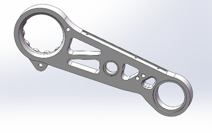
A closed section places material away from the neutral axis and gives the leg a useful torsional load path. I developed the hollow geometry around the existing leg configuration, keeping the bearing and transmission interfaces compatible with the surrounding assembly.
Composite fiber direction matters as much as external shape. I considered a torsion-oriented bias around 45° to the leg axis and discussed the actual placement with the workshop while participating in the layup process.
Making the shell and the interfaces together
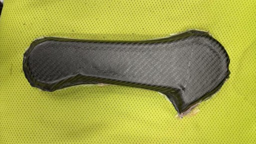
I compared internal-bladder and foam-supported forming routes against the part geometry and the available workshop processes. The selected route uses a PMI foam core, an external vacuum bag and autoclave curing to produce the composite blank.
Carbon-fiber plate inserts are incorporated at feature locations during molding. CNC finishing then creates the precision needed at the bearing seats and transmission interfaces. This lets the shell carry the structural load while machining controls the final assembly dimensions.
The workshop feedback fed directly into the CAD. Rounded transitions, accessible openings, manageable wall geometry and room for finishing all affected whether the part could be laid up, compacted, demolded and assembled.
| Design consideration | How it shaped the part |
|---|---|
| Fiber conformity | Round corners and transitions so the fabric can follow the shape. |
| Compaction and support | Use the PMI core and a consistent shell geometry during forming. |
| Assembly precision | Reserve critical features for CNC finishing after molding. |
| Layup access and demolding | Keep openings and wall features workable for the manufacturing process. |
Structural comparison and physical iteration
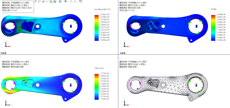
I used SolidWorks for the geometry and Simulation for geometry-led comparisons with directional material properties. This workflow let me compare stress patterns and torsional behavior while keeping design changes close to the CAD used for manufacturing.
The development ran through an initial design cycle, the first manufactured parts, hands-on checks and further workshop feedback. Fit, interlaminar bonding and local interfaces became central iteration points as the CAD turned into a usable part.
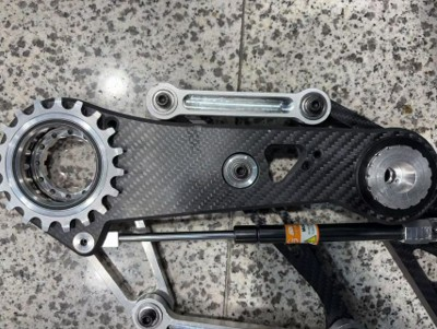
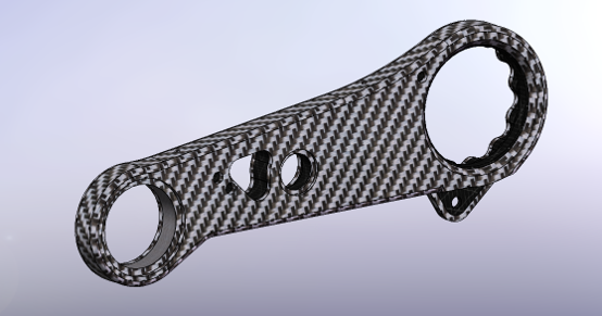
A manufactured version suitable for the robot was reached in May 2025. The photographs below connect the hollow CAD model, composite blank, simulation views and assembled leg.
Development
Identify the plate-leg problem
Start from the observed flex, vibration and mass of the existing machined leg.
Develop the hollow structure
Model the shell and compare structural alternatives while retaining the robot’s leg interfaces.
Work through the molding route
Select the PMI-core process, coordinate layup and make the first composite parts.
Refine the finished assembly
Use machining, assembly checks and workshop feedback to address fit and bonding details.
Project highlights
A lighter leg for the balance-infantry robot
The redesigned leg reduced mass by 50 g per leg. Jiaolong went on to win the RoboMaster 2025 national championship / First Prize.
Gallery